

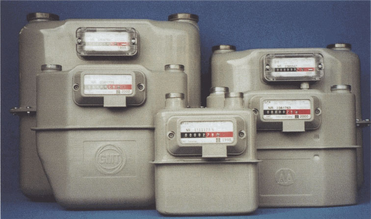
Diaphragm GAS MeterS
For domestic, commercial and industrial applications
General Information
Diaphragm meters have a tradition for an extended service life, a wide measuring range, long term measurement stability and maintenance free operation.
Main Elements
All diaphragm gas meters have pressed steel casings with an internal and external protective coating against corrosion. A measuring nodule is inserted into the casing to form a complete unit. There is a magnetic coupling that transmits the meter movement to the 8-digit index counter on the front panel. The meters have a maximum allowable working pressure (WP) of 0.1 bar.
Principle Advantages
- Fire safe to DIN 3374 and EEC requirements
- Synthetic diaphragms
- Unrestrained mounting of the measuring module
- Temperature range of -20°C to +60°C
- 4 pole suspended magnetic coupling
- Repeatable error curve
- Ease of installation - no upstream or downstream pipe requirements
- Low noise level
- Low pressure loss
- LF Pulse Output Option
All meters may he supplied with an optional LF pulse output with reed contact (volt free). This facility enables remote totalisation and is ideally suitable for energy management systems. For connection details see "LF Pulse Output Details" Data Sheet 2 which is supplied with each meter.
Installation
The gas must flow through the meter in the direction indicated on the meter. When viewed from the front looking at the index counter the gas flow is from left to right and the pipe connections should be:
- inlet connection - left hand side
- outlet connection - right hand side
When bringing the meter into operation care must be taken that any flow control devices in the line, before or after the meter, are opened slowly. This prevents meter overload due to excessive starting speeds. The line should always be shut off gradually.
Note: Diaphragm gas meters are precision measuring instruments manufactured to exacting tolerances and should be treated accordingly. Rough handling must he avoided. Excess pressure or any impact can cause damage to the metering unit, even if the casing shows no visible damage. Note that the maximum working pressure is 0.1 bar.
Typical Accuracy Curve
Diaphragm Meter Technical Details and Dimensions
|
Type |
Q max |
Q min |
Max WP bar |
LF Output |
Size |
Dimensions mm |
Weight Kg |
||||
|
A |
B |
C |
D |
E |
|||||||
|
GT2.5 |
4 |
0.025 |
0.1 |
0.01 |
20 Screwed |
110 |
212 |
69 |
208 |
162 |
1.9 |
|
G4 |
6 |
0.12 |
0.1 |
0.01 |
20 Screwed |
152 |
285 |
50 |
230 |
165 |
2.9 |
|
G6 |
10 |
0.06 |
0.1 |
0.01 |
25 Screwed |
250 |
291 |
85 |
330 |
199 |
4.0 |
|
G10 |
16 |
0.10 |
0.1 |
0.1 |
40 Screwed |
280 |
330 |
108 |
405 |
234 |
5.7 |
|
G16 |
25 |
0.16 |
0.1 |
0.1 |
40 Screwed |
280 |
330 |
108 |
405 |
234 |
5.7 |
|
G25 |
40 |
0.25 |
0.1 |
0.1 |
50 Screwed |
335 |
398 |
138 |
465 |
299 |
10.0 |
|
G40 |
65 |
0.40 |
0.1 |
1.0 |
80 Flanged |
510 |
675 |
172 |
684 |
376 |
66 |
|
G65 |
100 |
0.65 |
0.1 |
1.0 |
80 Flanged |
640 |
870 |
197 |
840 |
426 |
90 |
|
G100 |
160 |
1.00 |
0.1 |
1.0 |
100 Flanged |
710 |
1000 |
265 |
920 |
562 |
142 |
